- Quality Equipment Manufactured in Great Britain
<insert text>
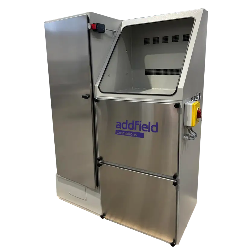
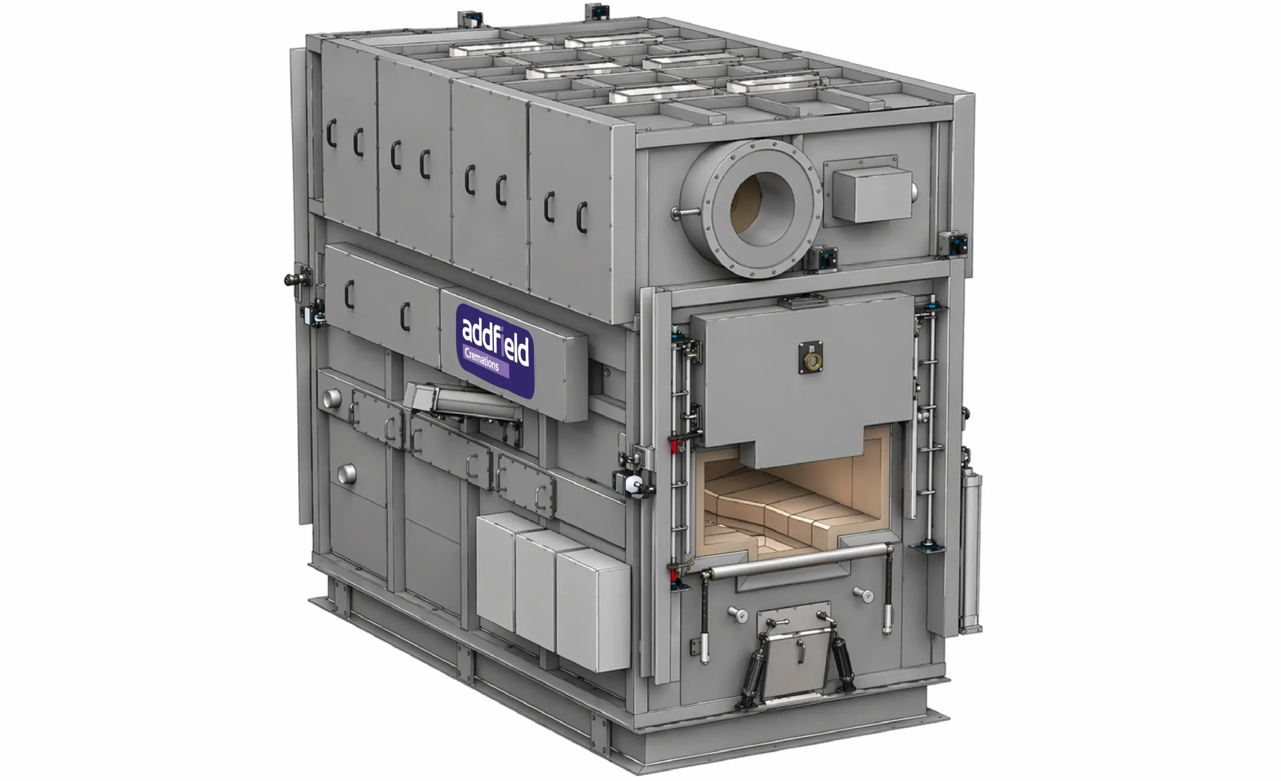
Expertly engineered to deliver reliable, efficient, and compliant performance. Manufactured in our facility in Staffordshire, Great Britain, built to the highest standards of quality and environmental responsibility. Our fossil fuelled pet cremator is designed to ensuring a dignified and dependable cremation process.
Each cremator can be supplied as a stand-alone unit, offering a flexible solution that can be seamlessly integrated into both new and existing facilities. Where applicable, the system can also be fitted with an advanced mercury abatement system helping to significantly reduce emissions and meet stringent regulatory requirements in specific country where it is required.
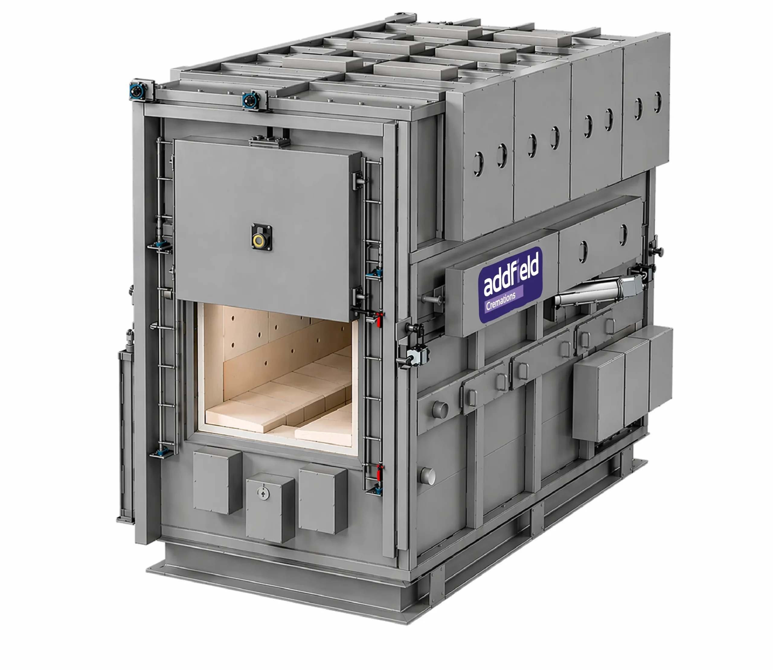
With a focus on durability, operational efficiency, and ease of use, the Addfield Human Cremators combines a robust construction with intelligent design. Supporting operators with dependable performance and long-term operation
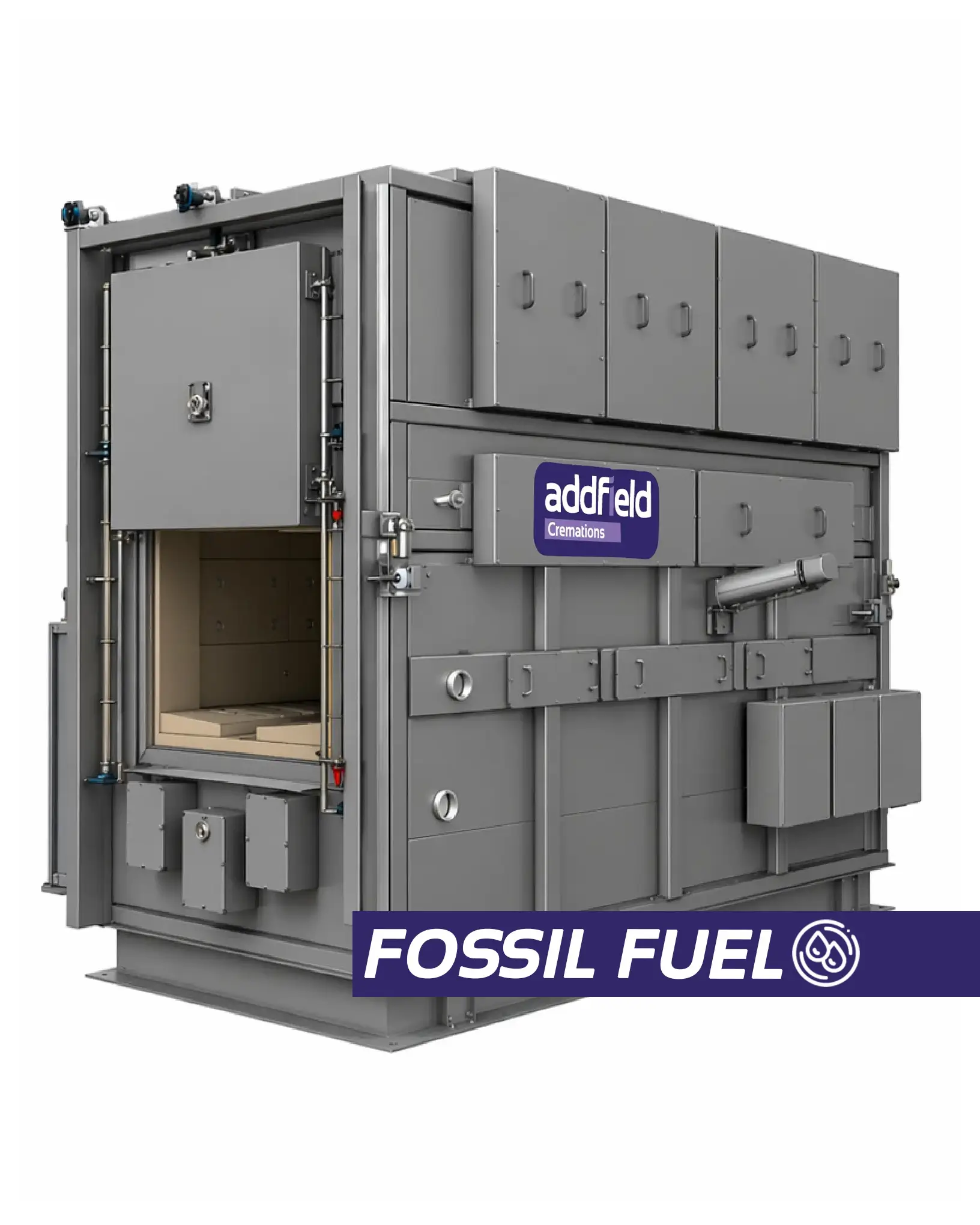
Internal Chamber Size:
| Width | 1000mm |
| Depth | 2800mm |
| Height | 700mm |
Specifications Overview:
| Combustion Type | Hot Hearth |
| Residence Time | Two Seconds |
| Secondary Chamber Operating Temperature | 850 deg.C (Minimum) |
| Flue Gas Treatment | Option Dry Filter (If required) |
| Fuel Types | Natural Gas LPG Diesel |
Dimensions are approximate
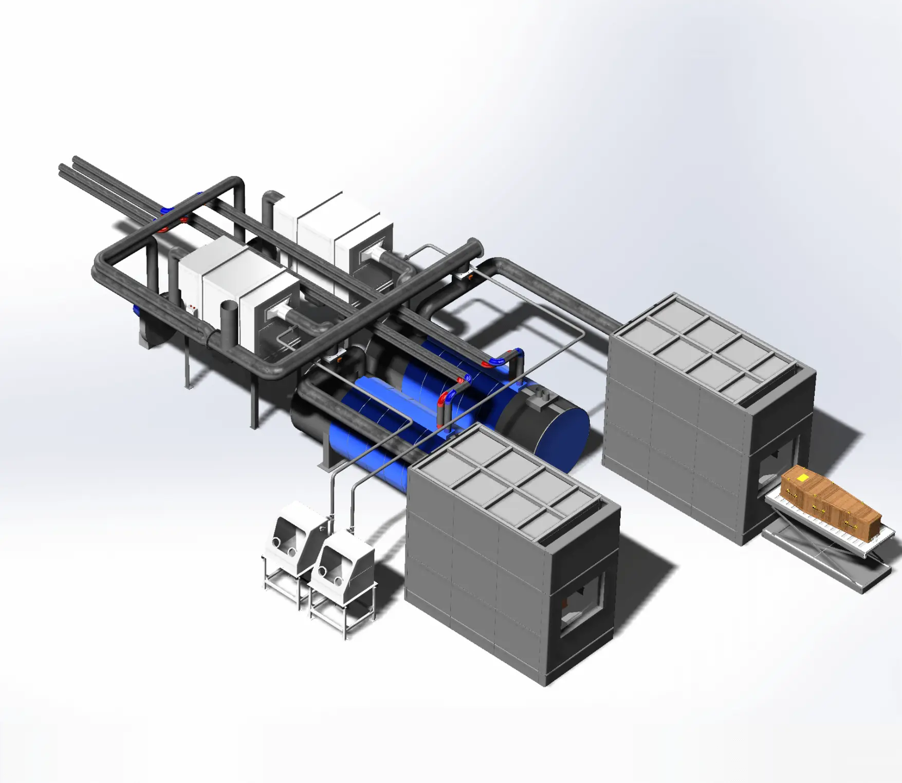
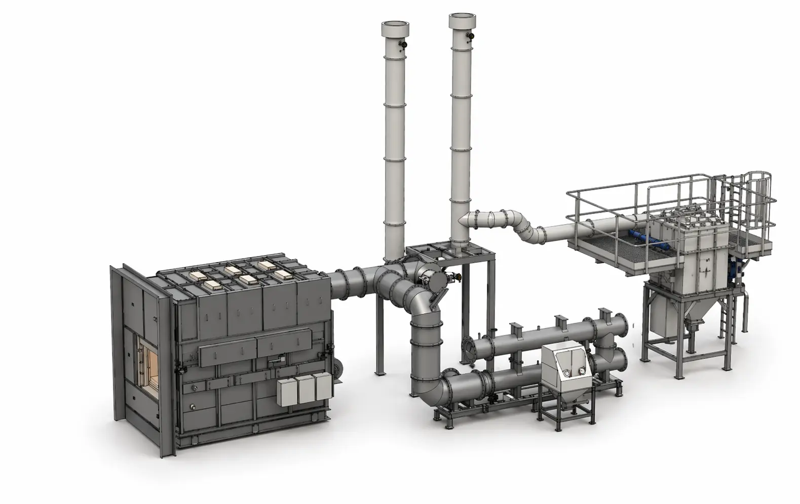
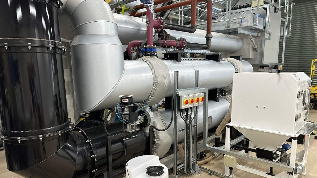
Human Crematorium Layout Plan
Click on various elements of the plant to find out more.
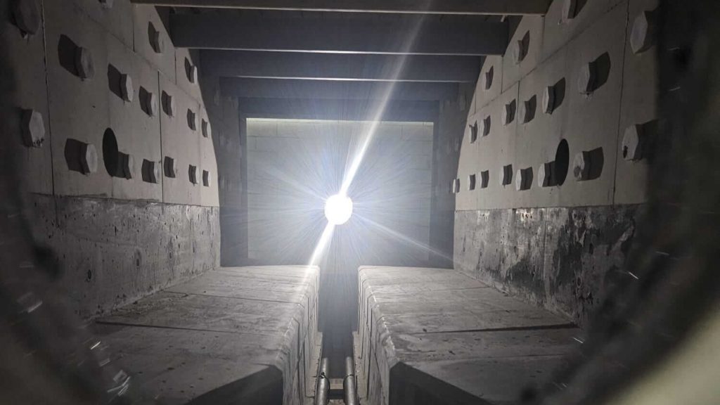
The Primary Combustion Chamber (PCC) would be configured as a fixed sloped and troughed hot hearth system.
The Fully Electric variants are equipped with 3 under hearth electrical elements and 6 further electrical elements situated in the PCC roof for preheat and combustion purposes. Additionally, an ElectraflameTM heater, unique to Addfield, would also be installed in the PCC to speed up initial ignition of the coffin and body and reduce the burn down period to achieve a good quality, fine, inert ash.
The Hybrid variants include one Hot Head Natural Gas Burner for Preheat and additionally one ElectraflameTM heater again unique to Addfield.
The Fossil Fuel would be equipped with one Gas or Oil fired Burner for Coffin Ignition and Preheat to achieve a good quality, fine, inert ash.
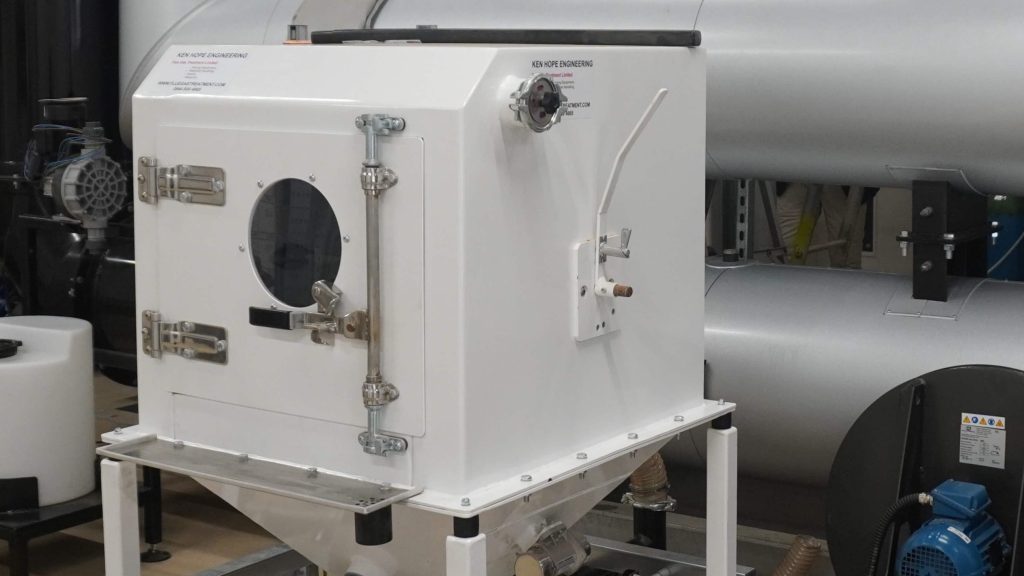
One pneumatic conveying and injection system designed to deliver the AddCleanTM reagent from individual 15kg (25litre) buckets into the exhaust gas stream.
A Selective Non-Catalytic Reduction (SNCR) De-NOₓ System injecting atomised 40% urea solution via an automatically retractable lance is installed in the hot gas ducting connecting the SCC exit to the Low-Pressure Hot Water Heat Exchanger (LPHWHE) or ‘hot water boiler’.
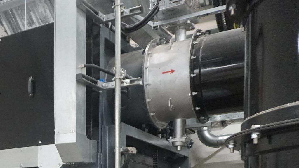
An exhaust system comprising of a variable speed induced draught (I.D) fan, which would draw the process gases through the entire system and direct them to a dedicated clean gas chimney. The exhaust system would be fitted with an PG5/2(25) compliant continuous emission monitoring system (CEMS), which would be linked to a control room-based SCADA system to provide a permanent and constant record of all flue gas emissions to the atmosphere.
To increase the reaction efficiency, the flue gas and reagents would then pass through a turbulent venturi section before passing to the filtration system within which the partially reacted AddcleanTM would be caught by the ceramic filter media, along with any particulate fly ash, and continue to react with the pollutants in the dirty flue gas.
The AddcleanTM neutralises any acidic gases such as HCl & SO2 whereas the activated carbon adsorbs any vapour phase heavy metals and dioxins/furans that may have reformed in the Waste Heat Recovery equipment under the process known as ‘De-Novo’ Synthesis typical occurring during less rapid flue gas cooling between 450 to 200°C.
The filter media, impregnated with Dioxin and NOx degrading catalyst, would capture, and discharge any residual particulate fly-ash together with the spent reagent materials, which would finally be automatically discharged into a sealed 205 litre metal drum.
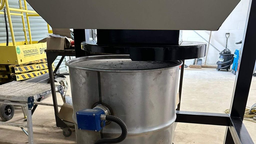
For the collection of filtered particulate matter and spent AddcleanTM reagent. The collected material is stored in a leak proof steel drum with overfill protection sensors.
Reverse jet pulsing is used to automatically clean accumulated particulate matter from the filter bags during operation. At predetermined intervals, a short burst of compressed air is injected into the top of a ceramic filter in the opposite direction to the normal gas flow. This rapid pulse causes the dislodging of ash and dust particles that have collected on its outer surface. The loosened material falls into a collection hopper below for removal. This process maintains airflow through the filtration system, minimizes pressure loss, improves emission control efficiency, and allows continuous operation without requiring the cremator to be shut down for manual filter cleaning.
The bypass valve incorporates a spring-to-close mechanism. In the event of a power failure, or any other fault requiring protective action, the release mechanism automatically opens, allowing the plant to safely vent to the bypass while the plant is brought to a controlled stop.
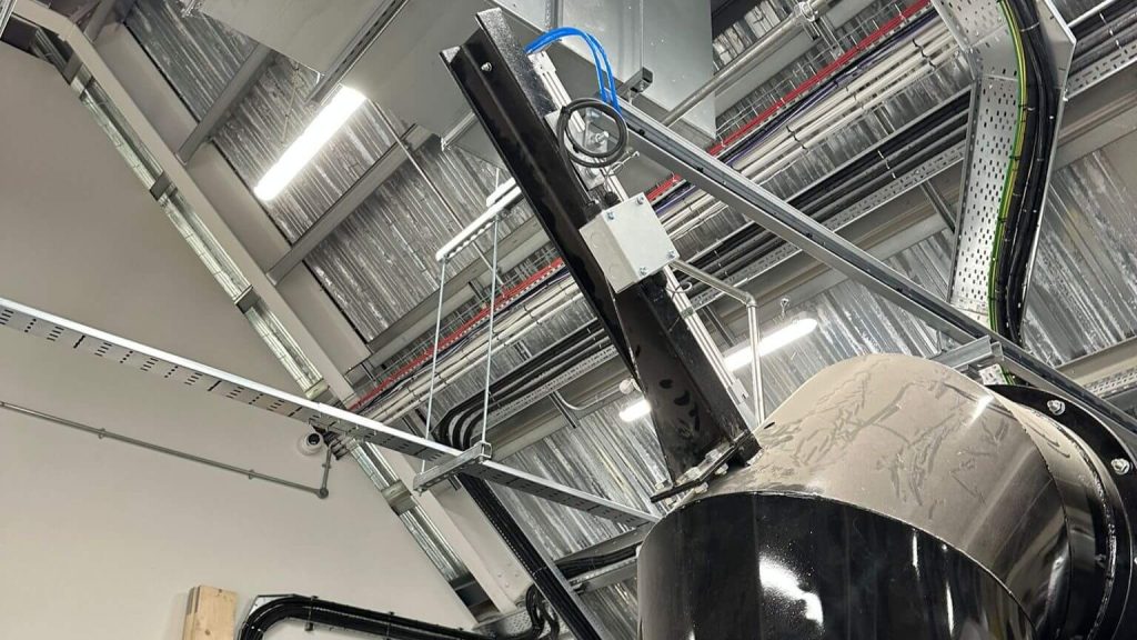
One high level duct, used only for the evacuation of the chamber flue gases under adverse conditions to allow a safe shutdown. Connected to a spigot on the secondary chamber hot gas ducting the duct would then be configured to connect to a dedicated by-pass chimney.
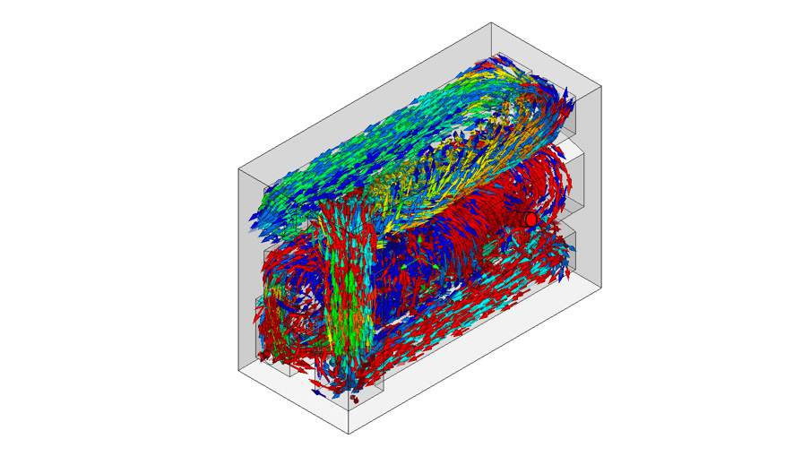
The Secondary Combustion Chamber (SCC) is located directly above the above the PCC, which provides a turbulent and high-temperature environment, via baffles and 6 electrical elements, for the thorough treatment and oxidation of the partially burnt flue gases produced during the PCC cremation process. The SCC would be arranged for the high-temperature operation at 800°C that is required for abated cremations as per PG5/2(25) and would have sufficient volume to ensure that all the treated products were resident for at least two seconds during all operating conditions including preheat, peak flow and steady state at 800°C.
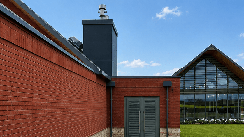
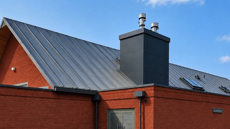
Serving as the exhaust outlet for gases generated during the cremation process. Its height and structure are carefully calculated to promote effective dispersion of exhaust gases while complying with environmental regulations.
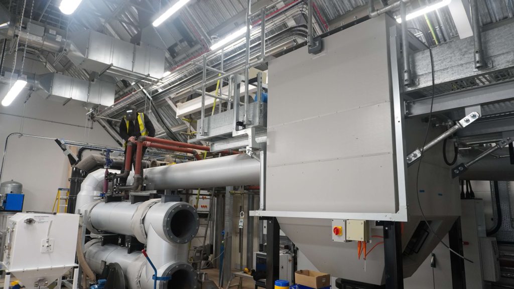
A waste heat recovery LPHWHE or ‘hot water boiler’ would be configured to reduce the flue gas temperatures to circa 200°C and produce hot water to pass to be automatically dissipated to atmosphere via an Air-Blast Cooler (ABC) and recirculated back to the LPHWE whenever the cremator was in operation.
Optionally the waste heat from this hot water can be used in the following way*:
*A Plate Heat Exchanger (PHE) can be supplied to deliver hot water to the client’s Central Heating Boiler CHB) system at circa 65°C.
The LPHWHE will be fitted with on-line compressed air shock blast cleaning valves to reduce instances of manual off-line cleaning.
Resulting fly-ash deposits would eventually need to be removed during manual cleaning required during maintenance periods.
Associated LPHWHE services such as duty standby water circulation pumps, expansion vessel and fill point would be included. Interconnecting pipework, valves, and strainers would also be provided.
The access platform on the Aurora human crematorium machine is a fixed purpose-built elevated working area designed to provide safe and convenient access to components that require routine inspection, maintenance, or repair, such as the flue system, emissions control equipment, fans, valves, sensors, and ceramic filter candles.